Published on August 25, 2020

Decoration of γ-Graphyne on TiO2 Nanotube Arrays: Improved Photoelectrochemical and Photoelectrocatalytic Properties

Applied Catalysis B: Environmental


First Author: bowen.gao

Keywords: graphyne , photocatalysis , photoeletrochemistry , TiO2 nanotube arrays

Abstract

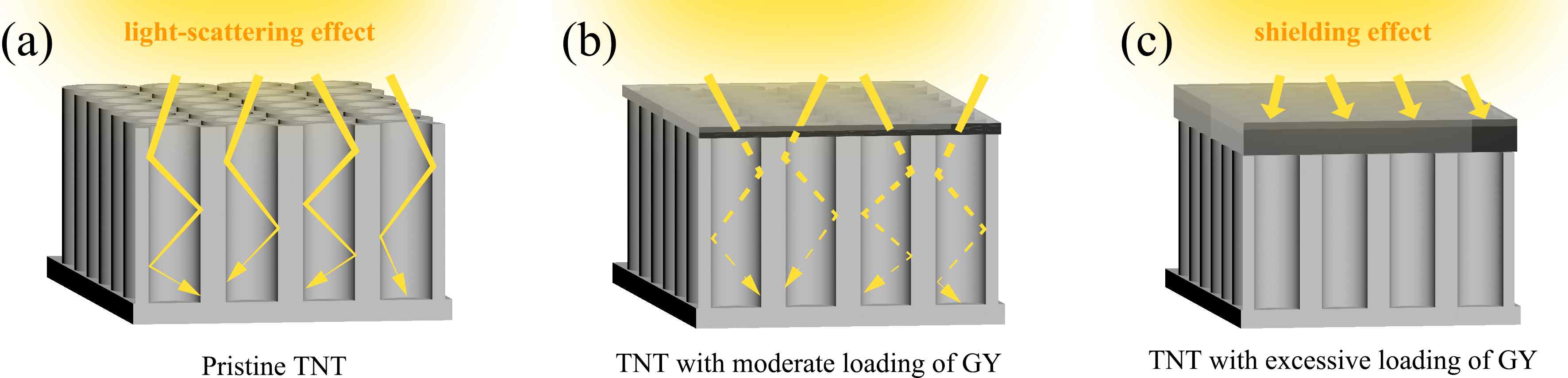
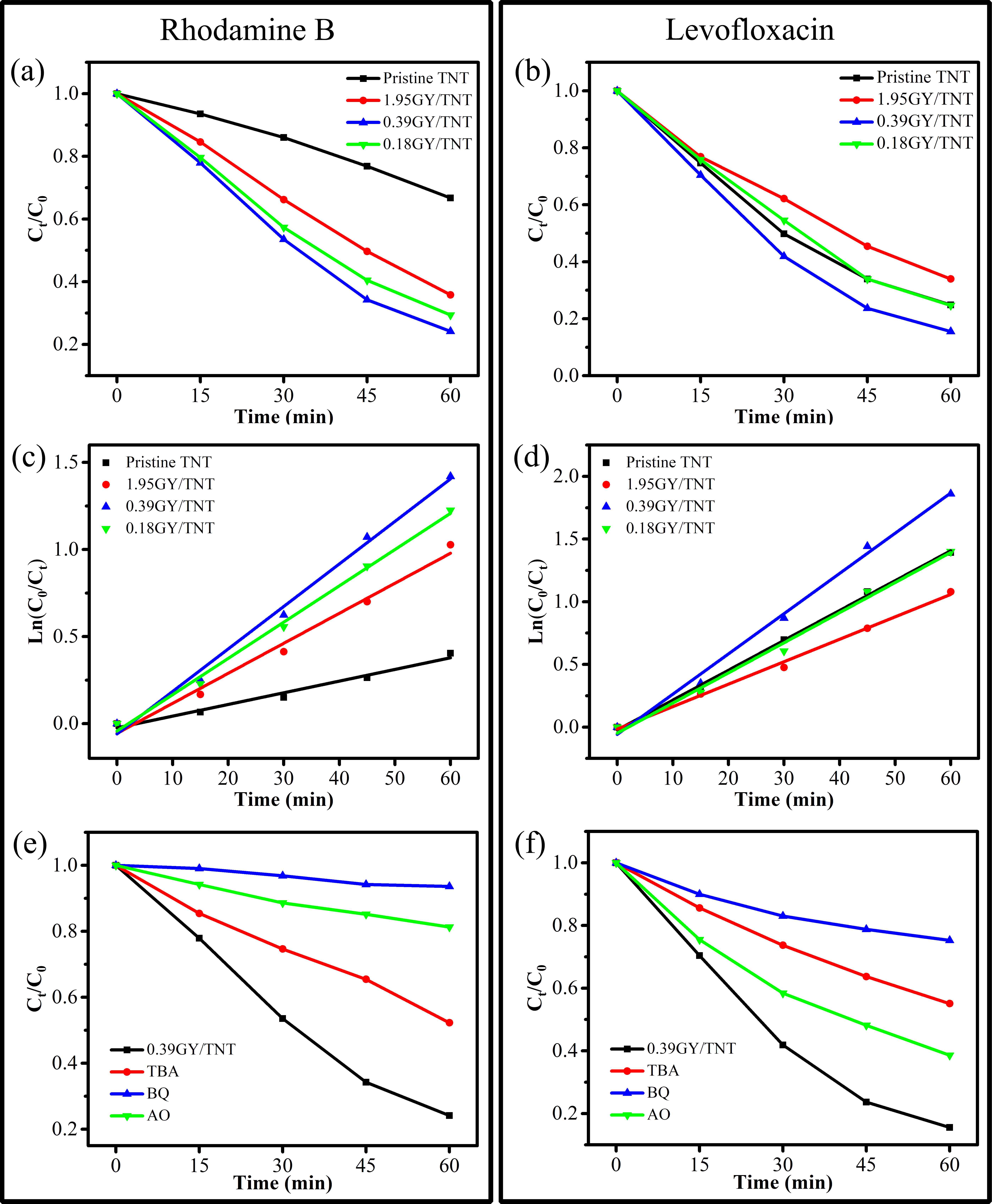
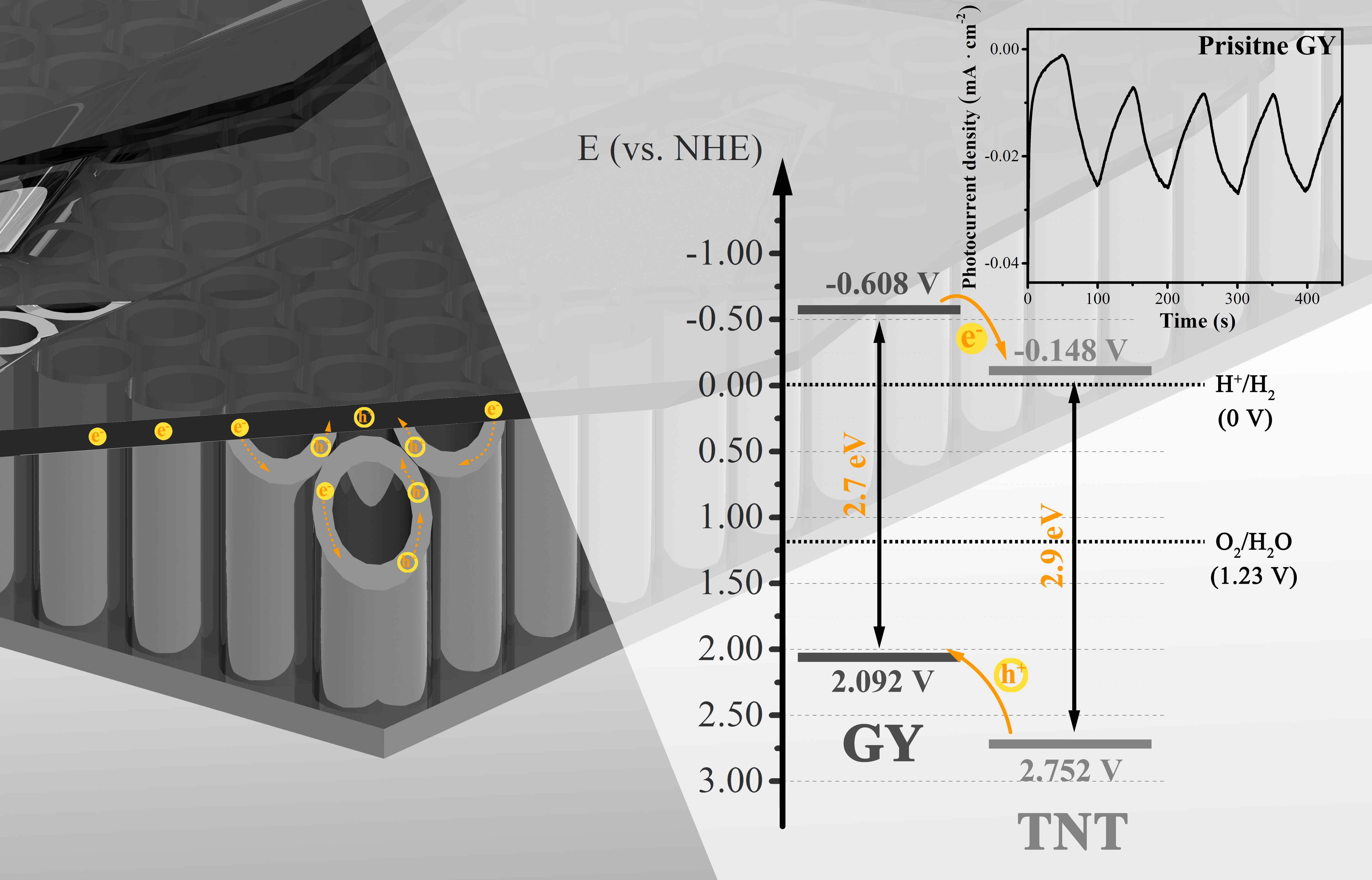
A series of γ-graphyne/TiO2 nanotube array heterostructures are first synthesized by a facile and environmentally friendly drop-coating method. The prepared heterostructures are completely investigated by a collection of characterizations. Interestingly, the unique C-O-Ti linkage between γ-graphyne and TiO2 nanotube arrays is verified by both X-ray photoelectron spectroscopy and Fourier transform infrared analysis. After modification of γ-graphyne, the maximum transient photo-current and photo-potential of TiO2 nanotube arrays are improved by 2.2 and 1.3 folds, respectively. Moreover, a maximum of 3.64 and 1.35 folds enhancements are severally verified for the photoelectrocatalytic degradation of levofloxacin and rhodamine B over the heterostructures compared to that of TiO2 nanotube arrays. Furtherly, the heterostructures also show superior photoelectrocatalytic performance on nitrogen fixation and oxygen evolution than TiO2 nanotube arrays. The crystal, morphological, photoelectrochemical, and photoelectrocatalytic stability of the heterostructures are confirmed. This work sheds light on designing γ-graphyne modified composites for photoelectrochemical and photoelectrocatalytic application.

Images

Schematic illustration for the synthesis of GY/TNT (a-c).

Fig. 1 Schematic illustration for the synthesis of GY/TNT (a-c).

TEM images (a), HR-TEM (b), SAED (c), XRD pattern (d), and EDS elemental mapping (e) of 0.39GY/TNT sample; The interplanar spacing (b, HR–TEM), dots spacing in the reciprocal lattice (c, SAED), and diffraction peaks (d, XRD) for anatase, graphyne, titanium {002} and titanium {001} are illustrated in red, green, yellow, and orange, respectively.

Fig. 2 TEM images (a), HR-TEM (b), SAED (c), XRD pattern (d), and EDS elemental mapping (e) of 0.39GY/TNT sample; The interplanar spacing (b, HR–TEM), dots spacing in the reciprocal lattice (c, SAED), and diffraction peaks (d, XRD) for anatase, graphyne, titanium {002} and titanium {001} are illustrated in red, green, yellow, and orange, respectively.

XPS spectra of 0.39GY/TNT: full-scale XPS spectrum (a), Ti 2p (b), O 1s (c), and C 1s (d, the dash-dot line depicted in cyan shows the XPS spectrum of pristine GY) XPS spectra.

Fig. 3 XPS spectra of 0.39GY/TNT: full-scale XPS spectrum (a), Ti 2p (b), O 1s (c), and C 1s (d, the dash-dot line depicted in cyan shows the XPS spectrum of pristine GY) XPS spectra.

Schematic illustration for light travel in pristine TNT (a), 0.39GY/TNT (b), and 1.95GY/TNT (c).

Fig. 4 Schematic illustration for light travel in pristine TNT (a), 0.39GY/TNT (b), and 1.95GY/TNT (c).

Photoelectrocatalytic degradation results (for rhodamine B (a) and levofloxacin (b)), corresponding pseudo-first-order kinetics (for rhodamine B (c) and levofloxacin (d)), and effects of different scavengers (for rhodamine B (e) and levofloxacin (f)) under UV–vis light irradiation.

Fig. 5 Photoelectrocatalytic degradation results (for rhodamine B (a) and levofloxacin (b)), corresponding pseudo-first-order kinetics (for rhodamine B (c) and levofloxacin (d)), and effects of different scavengers (for rhodamine B (e) and levofloxacin (f)) under UV–vis light irradiation.

Schematic illustration for the carrier transfer and plausible band structure of GY/TNT heterostructure under light activation; Inset shows the photo-current density over time of pristine GY under UV–vis light irradiation.

Fig. 6 Schematic illustration for the carrier transfer and plausible band structure of GY/TNT heterostructure under light activation; Inset shows the photo-current density over time of pristine GY under UV–vis light irradiation.